-
1 switchgear modules
Строительство: модули с распределительными устройствами -
2 модули с распределительными устройствами
Construction: switchgear modulesУниверсальный русско-английский словарь > модули с распределительными устройствами
-
3 параллельная система ИБП
параллельная система ИБП
-
[Интент]Parallel Operation: The system shall have the option to install up to four (4) UPSs in parallel configuration for redundancy or capacity.
1. The parallel UPS system shall be of the same design, voltage, and frequency. UPS modules of different size ratings shall be permitted to be paralleled together for purposes of increased capacity or UPS module redundancy. The UPSs in the parallel configuration shall not be required to have the same load capacity rating.
2. Parallel Capacity: With N+0 system-level redundancy, up to 2MW of load can be supported by the system.
3. Parallel Redundancy: With N+1 system-level redundancy, up to 1.5MW of load can be supported by the system, and only the UPS being replaced must be isolated from the source (bypass operation is not required for the entire system during the UPS replacement procedure).
4. Output control: A load sharing circuit shall be incorporated into the parallel control circuits to ensure that under no-load conditions, no circulating current exists between modules. This feature also allows each UPS to share equal amounts of the total critical load bus. The output voltage, output frequency, output phase angle, and output impedance of each module shall operate in uniformity to ensure correct load sharing. This control function shall not require any additional footprint and shall be an integral function of each UPS. The static bypass switches shall be connected in parallel.
5. Parallel System Controls: To avoid single points of failure, the UPS system shall have no single dedicated control system designed to control the operation of the parallel UPS system. Control of and direction of parallel UPSs shall take place via a master/slave relationship, where the first UPS to receive logic power asserts itself as a master. In the event of a master failure, a slave UPS shall take the role of master and assume the responsibility of the previous master UPS. Regardless of which UPS is master or slave, user changes to the system status, such as request for bypass, can be done from any UPS connected to the bus and all UPS on the bus shall transfer in simultaneously.
6. Communication: Communication between modules shall be connected so that the removal of any single cable shall not jeopardize the integrity of the parallel communication system. Load sharing communications shall be galvanically isolated for purposes of fault tolerance between UPS modules. A UPS module's influence over load sharing shall be inhibited in any mode where the UPS inverter is not supporting its output bus. Transfers to and from bypass can be initiated from any online UPS in the system.
7. Display: Each UPS multi-color LCD touch screen user interface shall be capable of using an active touch screen mimic bus to show the quantity of UPS(s) connected to the critical bus, as well as the general status of each UPS, such as circuit breaker status information. Any touchscreen display shall support the configuration of the [entire parallel] system and shall provide event and alarm data for all UPSs in the parallel configuration. A Virtual Display Application shall be available for download to the customer’s computer and shalll support remote monitoring of a complete system with up to 4 UPSs in parallel.
8. Battery runtime: Each UPS must have its own battery solution. The battery solution for the entire system can be a combination of standard and third-party batteries, but each UPS must use only one battery solution – either standard or third-party batteries.
9. Switchgear: A custom switchgear option shall be required for parallel operation.
[Schneider Electric]Тематики
EN
Русско-английский словарь нормативно-технической терминологии > параллельная система ИБП
-
4 parallel UPS system
параллельная система ИБП
-
[Интент]Parallel Operation: The system shall have the option to install up to four (4) UPSs in parallel configuration for redundancy or capacity.
1. The parallel UPS system shall be of the same design, voltage, and frequency. UPS modules of different size ratings shall be permitted to be paralleled together for purposes of increased capacity or UPS module redundancy. The UPSs in the parallel configuration shall not be required to have the same load capacity rating.
2. Parallel Capacity: With N+0 system-level redundancy, up to 2MW of load can be supported by the system.
3. Parallel Redundancy: With N+1 system-level redundancy, up to 1.5MW of load can be supported by the system, and only the UPS being replaced must be isolated from the source (bypass operation is not required for the entire system during the UPS replacement procedure).
4. Output control: A load sharing circuit shall be incorporated into the parallel control circuits to ensure that under no-load conditions, no circulating current exists between modules. This feature also allows each UPS to share equal amounts of the total critical load bus. The output voltage, output frequency, output phase angle, and output impedance of each module shall operate in uniformity to ensure correct load sharing. This control function shall not require any additional footprint and shall be an integral function of each UPS. The static bypass switches shall be connected in parallel.
5. Parallel System Controls: To avoid single points of failure, the UPS system shall have no single dedicated control system designed to control the operation of the parallel UPS system. Control of and direction of parallel UPSs shall take place via a master/slave relationship, where the first UPS to receive logic power asserts itself as a master. In the event of a master failure, a slave UPS shall take the role of master and assume the responsibility of the previous master UPS. Regardless of which UPS is master or slave, user changes to the system status, such as request for bypass, can be done from any UPS connected to the bus and all UPS on the bus shall transfer in simultaneously.
6. Communication: Communication between modules shall be connected so that the removal of any single cable shall not jeopardize the integrity of the parallel communication system. Load sharing communications shall be galvanically isolated for purposes of fault tolerance between UPS modules. A UPS module's influence over load sharing shall be inhibited in any mode where the UPS inverter is not supporting its output bus. Transfers to and from bypass can be initiated from any online UPS in the system.
7. Display: Each UPS multi-color LCD touch screen user interface shall be capable of using an active touch screen mimic bus to show the quantity of UPS(s) connected to the critical bus, as well as the general status of each UPS, such as circuit breaker status information. Any touchscreen display shall support the configuration of the [entire parallel] system and shall provide event and alarm data for all UPSs in the parallel configuration. A Virtual Display Application shall be available for download to the customer’s computer and shalll support remote monitoring of a complete system with up to 4 UPSs in parallel.
8. Battery runtime: Each UPS must have its own battery solution. The battery solution for the entire system can be a combination of standard and third-party batteries, but each UPS must use only one battery solution – either standard or third-party batteries.
9. Switchgear: A custom switchgear option shall be required for parallel operation.
[Schneider Electric]Тематики
EN
Англо-русский словарь нормативно-технической терминологии > parallel UPS system
-
5 feeder
- функциональный блок (в НКУ)
- распределительная цепь
- подающий механизм
- подающий аппарат
- питатель
- отходящая линия
- загрузочное устройство (для сыпучих материалов)
- дозатор (металлургия)
- блок вывода
- автоматический выключатель защиты отходящих линий
автоматический выключатель защиты отходящих линий
-Параллельные тексты EN-RU Distribution busbars, branched directly from the main busbar system, are vertically installed either on the right or on the left in the column.
They feed the outgoing circuit-breakers and are connected to them by means of rigid or flexible copper busbars, or cables.
[ABB]Распределительные шины расположены вертикально в правой или в левой части секции и подсоединены непосредственно к главным шинам.
Они подают питание на автоматические выключатели защиты отходящих линий через жесткие или гибкие медные шины или через кабели.
[Перевод Интент]Тематики
- НКУ (шкафы, пульты,...)
- выключатель автоматический
- электроснабжение в целом
EN
блок вывода
Функциональный блок, через который обеспечивается питание одной или нескольких выходных цепей.
[ ГОСТ Р 51321. 1-2000 ( МЭК 60439-1-92)]EN
outgoing unit
functional unit through which electrical energy is normally supplied to one or more external circuits
[ IEC 61439-1, ed. 2.0 (2011-08)]FR
unité de départ
unité fonctionnelle à travers laquelle l'énergie électrique est normalement fournie à un ou plusieurs circuits externes
[ IEC 61439-1, ed. 2.0 (2011-08)]Параллельные тексты EN-RU
The 115-70 combined busbar allows connection of a Masterpact NW08-32 type circuit-breaker at the top of the cubicle and installation of MCC / PCC feeders in the 36 bottom modules.
[Schneider Electric]Применение комбинированных шин с межосевым расстоянием 115-70 мм позволяет присоединить к ним в верхней части шкафа автоматический выключатель Masterpact NW08-32, а в нижней части (36 модулей по высоте) - блоки вывода, выполняющие функцию управления электродвигателями или распределения электроэнергии.
[Перевод Интент]Тематики
- НКУ (шкафы, пульты,...)
Классификация
>>>EN
FR
дозатор
Устр-во для дозирования массы или объема жидких и сыпучих материалов. Различают д.: весовые и объемные, периодич. и непрер. действия, одно- и многокомпонентные. К объемным д. периодич. действия относят бункерные, коробчатые, поворотные, шиберные. Весовые д. периодич. действия конструктивно представляют обычные рычажные весы. Весовые д. непрер. действия сочетают в одном агрегате устр-во для взвешивания и регулирования подачи материала и применяются в осн. в автоматич. произ-ве.
[ http://metaltrade.ru/abc/a.htm]Тематики
EN
загрузочное устройство (для сыпучих материалов)
—
[ http://slovarionline.ru/anglo_russkiy_slovar_neftegazovoy_promyishlennosti/]Тематики
EN
FR
На отходящих линиях аппараты управления могут быть установлены либо на каждой линии, либо быть общими для нескольких линий.
ВУ, ВРУ, ГРЩ должны иметь аппараты защиты на всех вводах питающих линий и на всех отходящих линиях.
[ПУЭ. Раздел. 7]Тематики
EN
питатель
Устройство для подачи насыпных и штучных грузов из загрузочных устройств к транспортирующим или перерабатывающим машинам
[Терминологический словарь по строительству на 12 языках (ВНИИИС Госстроя СССР)]Тематики
- строит. машины, оборуд., инструмент прочие
EN
DE
FR
подающий аппарат
Механизм пилигримового стана, обеспеч. возвр.-поступат. движение дорна и гильзы в процессе раскатки.
[ http://metaltrade.ru/abc/a.htm]Тематики
EN
распределительная цепь
Электрическая цепь, питающая один или более распределительных щитов
[826-14-02]
[ ГОСТ Р МЭК 60050-826-2009]
распределительная цепь
Электрическая цепь от этажного щитка до квартирного.
[ ГОСТ Р 51628-2000]EN
distribution circuit
electric circuit supplying one or more distribution boards
[IEV number 826-14-02 ]FR
circuit de distribution, m
circuit électrique alimentant un ou plusieurs tableaux de répartition
[IEV number 826-14-02 ]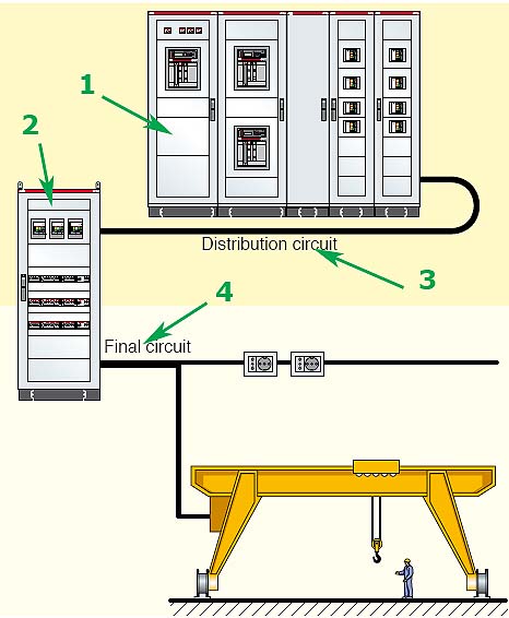
Рис. ABB
1 - Главный распределительный щит (ГРЩ)
2 - Распределительный щит;
3 - Распределительная цепь
4 - Групповая цепьТематики
EN
DE
- Verteilungsstromkreis, m
FR
- circuit de distribution, m
функциональный блок
Часть НКУ, содержащая электрические и механические элементы и обеспечивающая выполнение одной функции.
[ ГОСТ Р 51321. 1-2000 ( МЭК 60439-1-92)]
функциональный блок
Часть взаимосвязанных аппаратов ВРУ или панели (многопанельного ВРУ), обеспечивающая выполнение определенной функции по 3.1.1.
Примечание — Аппараты блока могут быть не объединены единой съемной конструктивной основой
[ ГОСТ Р 51732-2001]
функциональный блок
Часть НКУ, содержащая электрические и механические элементы, включая коммутационные устройства, и обеспечивающая выполнение одной функции.
Примечание — Проводники, соединенные с функциональным блоком, но являющиеся внешними по отношению к его отсеку или к оболочке защищенного пространства (например кабели вспомогательных цепей, соединенные с общим отсеком), не являются частью функционального блока.
[ ГОСТ Р МЭК 61439.1-2013]EN
functional unit (of an assembly)
a part of an assembly of switchgear and controlgear comprising all the components of the main circuits and auxiliary circuits that contribute to the fulfilment of a single function
NOTE – Functional units may be distinguished according to the function for which they are intended e.g.: incoming unit, through which electrical energy is normally fed into the assembly, outgoing unit through which electrical energy is normally supplied to one or more external circuits.
[IEV number 441-13-04 ]FR
unité fonctionnelle (d'un ensemble)
partie d'un ensemble comprenant tous les éléments des circuits principaux et des circuits auxiliaires qui concourent à l'exécution d'une seule fonction
NOTE – Les unités fonctionnelles peuvent se différencier selon la fonction pour laquelle elles sont prévues, par exemple: unité d'arrivée par laquelle l'énergie électrique est normalement fournie à un ensemble, unité de départ par laquelle l'énergie électrique est normalement fournie à un ou plusieurs circuits externes.
[IEV number 441-13-04 ]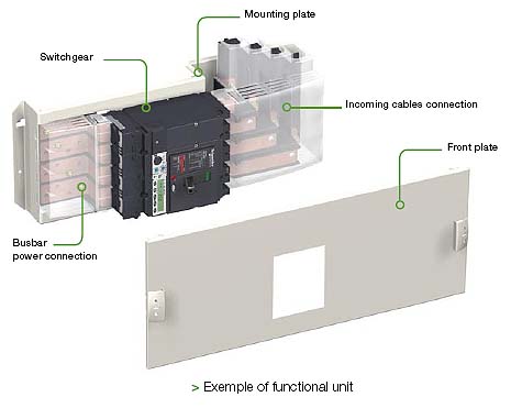
Пример функционального блока
Тематики
- НКУ (шкафы, пульты,...)
Классификация
>>>EN
DE
FR
Англо-русский словарь нормативно-технической терминологии > feeder
См. также в других словарях:
параллельная система ИБП — [Интент] Parallel Operation: The system shall have the option to install up to four (4) UPSs in parallel configuration for redundancy or capacity. 1. The parallel UPS system shall be of the same design, voltage, and frequency. UPS modules of… … Справочник технического переводчика
Diesel generator — A Cummins diesel generator of 500kVA in a tourist resort in Egypt … Wikipedia
Maxwell Technologies — Type Corporation Industry Energy storage Founded … Wikipedia
Diesel locomotive — Three styles of diesel locomotive body: cab unit, hood unit and box cab. These locomotives are operated by Pacific National in Australia … Wikipedia
Ericsson — Infobox Company company name = Telefonaktiebolaget L. M. Ericsson company company type = Public (OMX|SSE101|ERIC B) (nasdaq|ERIC) company slogan = Taking You Forward foundation = Stockholm, Sweden (1876) founder = Lars Magnus Ericsson location =… … Wikipedia
Military equipment of Turkey — The military equipment of Turkey includes a wide array of arms, artilleries, large surface vessels, cannons, armored vehicles, mortars, unmanned vehicles and many different equipments. Contents 1 Historical development 1.1 General 1.2 1923 1950 … Wikipedia
Chemlink — is a brand name for wireless video transmission products made by the [Chung Hsin Electric and Machinery Manufacturing Corporation]http://www.chem.com.tw/ (CHEM) Wireless Communication Division. They focus on a 5.8GHz wireless transmission for… … Wikipedia
DC injection braking — DC injection brake module [1] DC injection braking is a method of slowing AC electric motors. A DC voltage is injected into the winding of the AC motor after the AC voltage is disconnected, providing braking force to the rotor [2] … Wikipedia